Arnav Prasad
Practices robotics, mechanical design, programming, and educating.
SWERV3: A Swerve Drive Robot
A collaboration with Zachary Thé: thezach@udel.edu
What is "Swerve Drive"?
Swerve Drive, also known as Pivot Drive, is a holonomic drive train setup. Each wheel is independently driven, and independently steered. These added degrees of freedom allow a robot to move in any direction, regardless of chassis orientation. Unlike other holonomic drive systems, such as omni wheels or mecanum wheels, swerve offers several advantages. A few are listed below:
- Agility: Swerve is a true 2D drive system, in which drive direction and power may be completely divorced from chassis orientation.
- Traction: Unlike omni or mecanum wheels, swerve drive allows the user to vector the full drive force in any desired direction. Additionally, swerve uses any normal wheel (including high-traction), whereas omni and mecanum wheels have rollers, providing axes of slip.
- Flexibility: A swerve chassis allows for numerous control input methods (robot-centric, driver-centric, etc), allowing a user to switch on the fly to whatever is most intuitive at the moment.
Mechanical Design
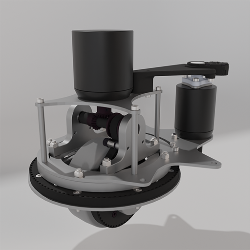
As shown in the image above, each swerve module, or pod, has two brushless DC motors (BLDCs). One BLDC, mounted above the wheel, is used to power the wheel itself. It transfers power to the wheel using miter gears (to reorient the torque 90°), and a timing belt/pulleys. The second BLDC is used to pivot the wheel relative to the pod, vectoring the drive force at any angle. The turning setup here uses a timing belt and pulleys with a 7:1 reduction, allowing for fine adjustment of the steering angle.
Of course, it is important to always know at what angle the pod is currently steered. To keep track of this, a REV Robotics Through-Bore Encoder is coupled to the turning BLDC, mounted above it. Due to the belt reduction, however, "0" on the encoder is not necessarily "0" for the pod upon startup. To get around this issue, each pod is fitted with a hall effect sensor fixed to the static plate, and has an embedded magnet in the 3D printed, large ring pulley located around the wheel. On startup, each pod will "home" using the hall sensor and magnet, providing a consistent 0 location offset.
For ease of manufacturing, most parts for this design are one of the following:
- 3D Printed: Parts are printed out of PETG (FDM) when strengh is needed, or SLA Resin when fine detail is required.
- Flat Aluminum Plates: Keeping all parts flat (or at least only having 2D geometry) allows for rapid manufacturing by a laser cutting service, such as SendCutSend.
- Commercial, off-the-shelf (COTS): Hardware such as bearings, bolts, nuts, belts, etc. were selected to be readily-available off of well known commercial vendors.
Software & Programming
Central Control
Currently, the robot will be run using ROS 2. ROS will be run on a Rasperry Pi Model 4, with 8GB of RAM available. The central controller will be responsible for several tasks, including:
- Receiving or calculating the robot's drive commands
- Calculating the angle and power of each swerve pod based on desired motion
- Commanding each swerve pod to move as instructed
- (Future Addition) Mapping the robot's environment and localizing using cameras / LIDAR / Odometry
If it becomes evident that a single Raspberry Pi 4 is not sufficient, then more may be added. Additionally, for certain image-processing based tasks, an NVidia Jetson Nano is being considered.
Pod Control
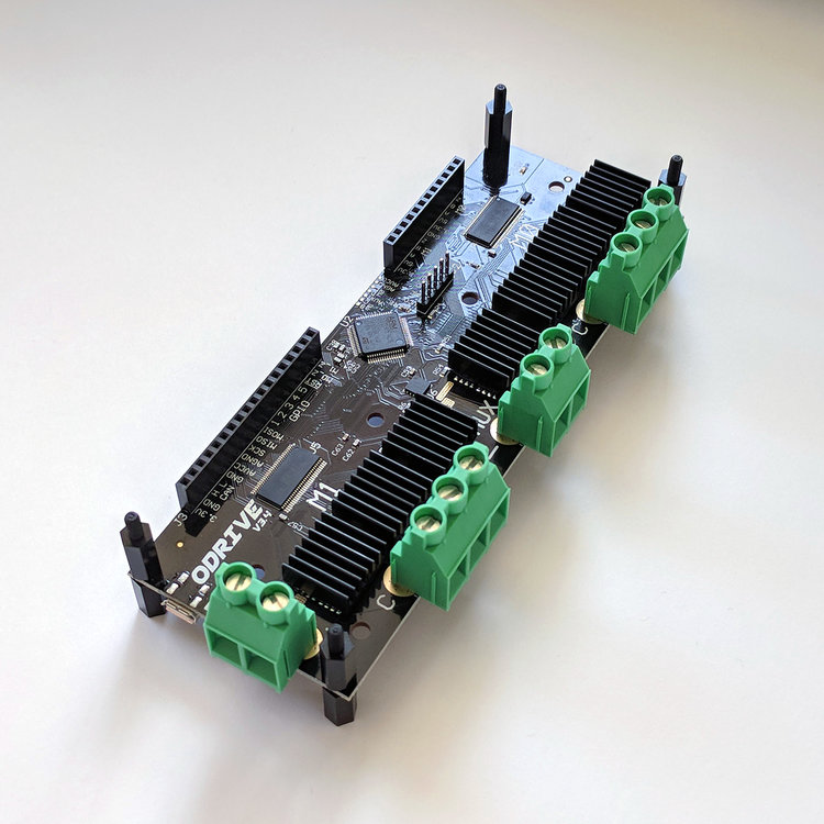
Each swerve pod is run by an individual ODrive V3.6. The ODrive V3.6 can control up to 2 motors, which is perfect for one swerve pod. Each motor on the ODrive has its own encoder allotment. For the turning motor, the aforementioned, high-resolution REV Robotics Through-Bore Encoder is used. For the drive wheel, where detailed feedback is not necessary, we use the built-in hall-effect sensors that come pre-installed in the drive BLDC motor.
Once tuned, the ODrive handles all of the motor control on board. A commanded velocity or position is set, and the ODrive will handle the necessary PIDs to move the motor accordingly. This was one of the reasons the ODrive was chosen; off-boarding the pod PID loops from the central Raspberry Pi controller helps to unburden the Pi, allowing it to focus on other tasks.
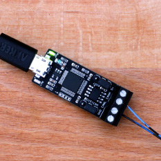
The central Raspberry Pi controller communicates with each pod's ODrive using a CANbus network. CAN was chosen for its resilience in the presence of noise, especially over long lengths of wire. USB was unfortunately not robust enough, due to the electromagnetic interference from the high frequency motors and other components. To use CANbus on the Raspberry Pi, a USB-CAN adapter is needed. We use the CANable.
Swerve Control Calculations
Thankfully, when figuring out the swerve control calculations, we're not starting from square 1. Swerve is a popular drive system used in the FIRST Robotics Competition (FRC), and as such, many teams provide documentation that can be followed. One phenomenal example is the white paper written specifically on a 3-wheel swerve drive by Team 1640 Sab-BOT-age. The whitepaper can be found here.
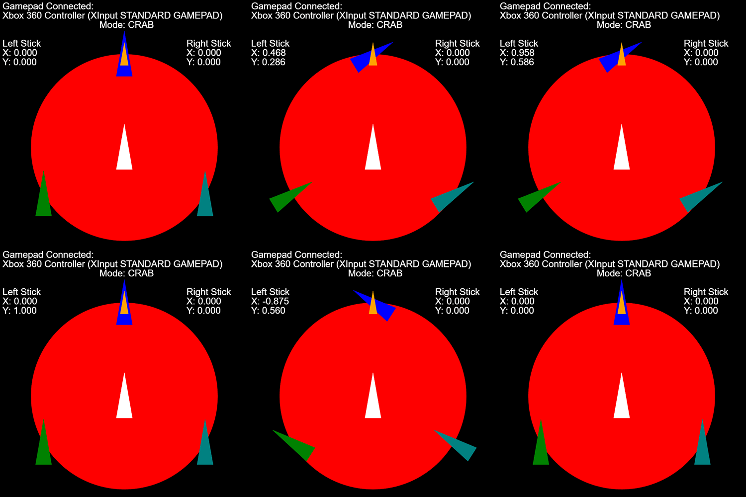
While the whitepaper describes the basic elements of writing the swerve control algorithms, seeing it in action helps understand why the equations work. Unfortunately, since the robot isn't ready yet (and running untested code on hardware is always dangerous...) seeing it fully in action isn't possible. Instead, I have created a browser-based "simulator" using P5.js, which takes gamepad input and moves graphics on-screen, so I can test my code as I write it. The GIF below shows the basic functionality, and the full code is available on my GitHub .
Auxilliary Features
Given my background in FIRST, what robot would be complete without the ability to pick balls up off the floor and launch them across a room? While certainly not a priority for this project, plans are in place to have some sort of collection system and launcher on board. These features are mostly for fun, but also give the robot operator dyanmic objectives -- chasing balls around the floor, and lining up to launch them. These tasks will help with learning to operate such a unique drive system, and expose potential bugs in the control logic.
Due to familiarity and availability, the auxilliary systems will be actuated and controlled using parts from REV Robotics:
The Spark MAX motor controller and the NEO 550 brushless motor are designed to work together. The NEO has a built-in hall effect sensor that plugs into the Spark MAX, allowing for easy position or velocity control. Additionally, the Spark MAX controllers are able to be controlled over CANbus, allowing us to add them into the same CAN network that the ODrives will be a part of.
Robot Power
The robot's main power pack consists of 40 Molicel P42A cells. The cells are configured in a 10S4P configuration, providing a nominal 42V, with a continuous output current capability of 180A. The battery will have 4200mAh, allowing for a long run time before stopping to recharge.
While the ODrive motor controllers can handle up to 56V, the auxilliary Spark MAX controllers cannot. A secondary on-board battery will be installed on the robot to handle (and mostly isolate) the auxilliary systems. This battery uses the same Molicel P42A cells as the main pack, but only 18 of them. They are arranged in a 6S3P configuration, providing a nominal 24V, with a continuous output current capability of 135A. The auxilliary battery will have 2520mAh, and will recharge from the main battery as needed.
For safety, each battery is enabled through the use of a Flipsky Anti-Spark Switch. This switch minimizes the inrush current, protecting the sensitive electronics.
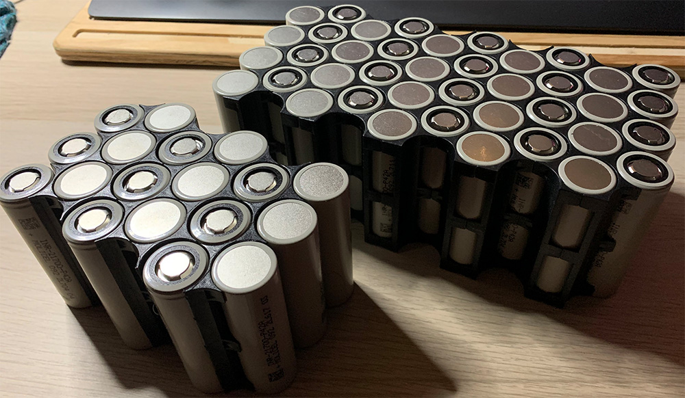
The battery construction was provided by Black Fox Boards