Arnav Prasad
Practices robotics, mechanical design, programming, and educating.
Junior Design: Denesting Thermoplastic Clamshells
Group Project for MEEG304 at the University of Delaware
Background and Problem Statement
At the University of Delaware, Mechanical Engineering Juniors take MEEG304 - Informally called "Junior Design." As a part of this course, we are split into teams, and each team has a project from local sponsors. When I took this course, my sponsor was Siemens Healthineers.
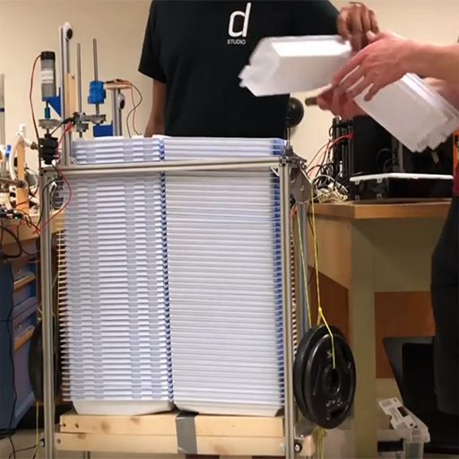
On the manufacturing floor at Siemens, workers recieved stacks of thermoformed plastic clamshells which had to be manually separated, before they could be filled with product. Siemens wanted a more elegant solution.
Project Scope
"Design and prototype a de-nesting machine for thermoformed clamshells that operates quickly, safely, and in a controlled manner."
Constraints and Targets
| Constraint | Target Value |
|---|---|
| Cost | < $5,000 |
| De-nesting speed | 4 seconds / clamshell |
| Footprint | ≤10ft2 |
| Force applied to single point on clamshell | < 47N |
| Prototype Fatigue Test | > 250 cycles |
| Interface Height (Ergonomics) | 0.8m - 1.3m from floor |
| Operating Voltage | 110VAC |
| Available Air Pressure | 80PSI |
| Safety | 0 sharp edges, pinch points, other hazards |
Selected Solution
Cylindrical Cams
After considering multiple options, the most elegant solution to this problem was to use a cylindrical cam to separate the clamshells. A cylindrical cam can be thought of as a screw - or more simply, a ramp spiraled around a cylindrical core. The cams would be positioned such that the lip of the clamshell would enter the spiral at the bottom, and as the cam rotated, the clamshell would be pulled upwards from the stack.
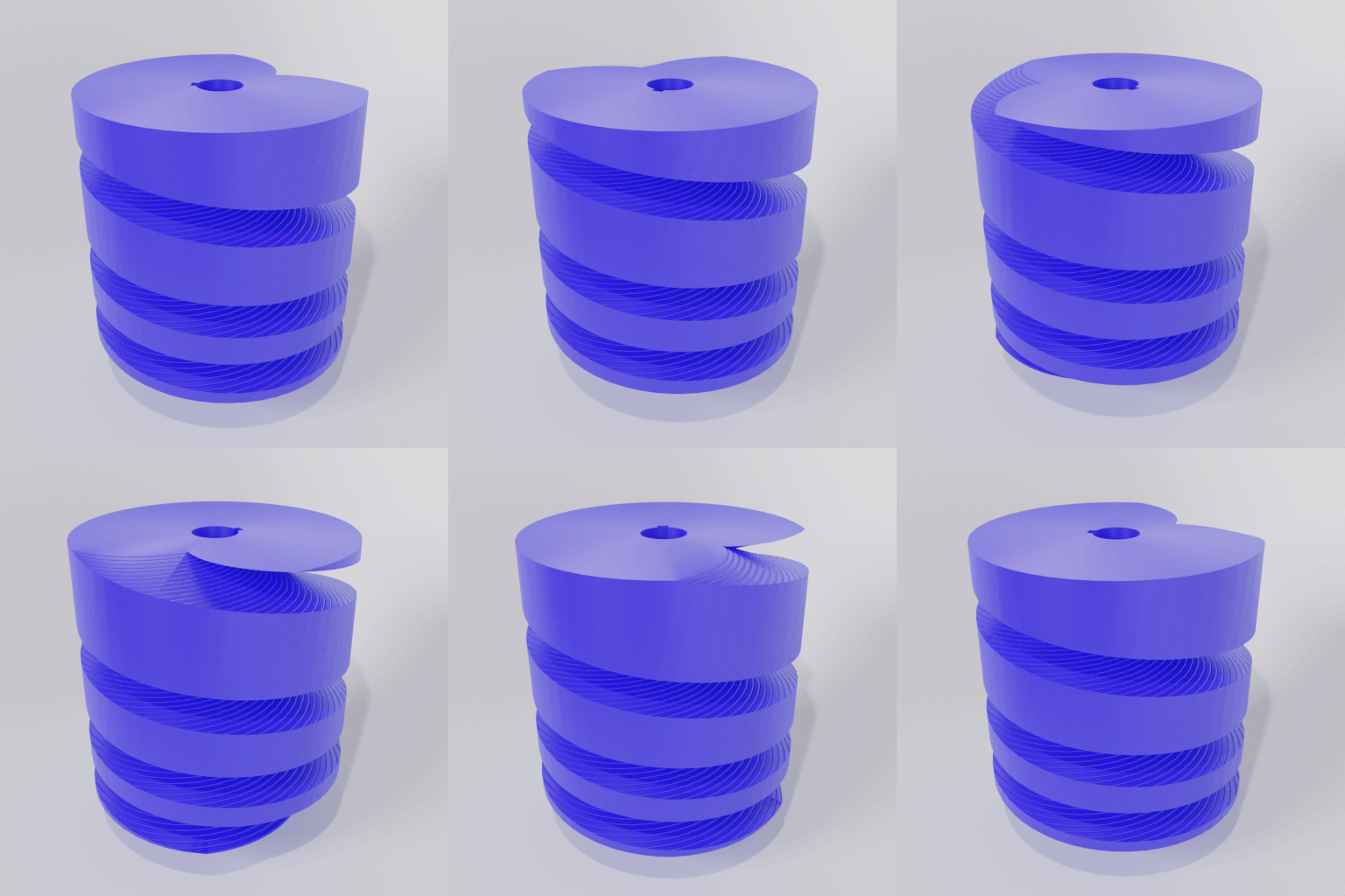
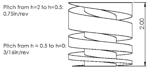
A point of interest in the cylindrical cam is the varied pitch. As pictured, the pitch is larger at the top of the cam than at the bottom. This is to increase the separation between clamshells as the cam rotates. Early prototypes of our cam had a constant pitch, and while this did effectively elevate the clamshells, there was often not enough room to reach between them and separate just the top clamshell.
Structure and Platform
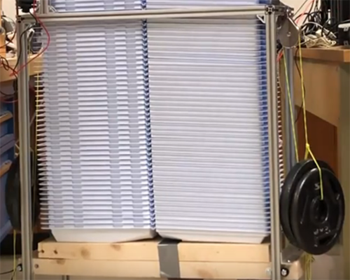
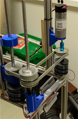
We built the frame of the machine out of 8020 aluminum t-slot extrusion. This material allowed us to have a rigid platform that was easily adjustable while we were prototyping. Additionally, many rollers that ride in the t-slot grooves are readily available. This allowed us to easily design and test a platform that would keep the clamshells feeding into our cams. For the prototype, we attached weights on either end of the platform, but proposed a solution using constant force springs for the final product. The 8020 structure also provided us with the flexibility needed to mount other components, such as the motor, timing pulleys, and electronics.
Control System
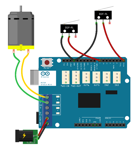
The brains behind the whole system was an Arduino Uno, and an Arduino Motor Shield to drive the DC motor. Our system also used two limit switches.
The first limit switch (L1) was used to trigger the system. It was positioned above the stack of clamshells, so as the top clamshell was removed, L1 was pressed. When L1 was pressed, the arduino would drive the motor to ready the next clamshell for removal.
The second limit switch (L2) was used in place of a motor encoder, for simplicity. One of the drive shafts had a 3D printed tab added to it. This tab would press L2 once per rotation. When L1 was triggered, the arduino would turn on the motor until L2 was pressed, and then stop again. This way, we could ensure that one rotation was completed each time the system was triggered.
Constraint Validation
| Constraint | Target Value | Measured Value | Pass/Fail |
|---|---|---|---|
| Cost | < $5,000 | $598.68 | Pass |
| De-nesting speed | 4 seconds / clamshell | 2.5 seconds / clamshell | Pass |
| Footprint | ≤10ft2 | 1.4ft2 | Pass |
| Force applied to single point on clamshell | < 47N | ≤ 40N | Pass |
| Prototype Fatigue Test | > 250 cycles | 100 cycles | Fail |
| Interface Height (Ergonomics) | 0.8m - 1.3m from floor | 1.05m | Pass |
| Operating Voltage | 110VAC | 110VAC | Pass |
| Available Air Pressure | 80PSI | None | Pass |
| Safety | 0 sharp edges, pinch points, other hazards | 6 sharp edges, 6 pinch points, 2 impalement hazards, 2 suspended weights | Fail |
Overall, our prototype met most of our constraints. We proposed solutions for the 2 which we failed:
- Fatigue Test: The point of failure was the motor mount, which loosened over time. A more
secure mount would solve this problem.
- Safety: Due to time constraints of the course, we were unable to polish up the prototype.
Long shafts should be cut down, and plastic guards should be fitted over all moving parts. The weights should be
replaced with enclosed springs, which will be safer.